
#MINIM OSD V1 1 CODE#
Please see the file uploaded under the files tab for Developer credits, Links to source code and other information! +5V 500mA regulator for up to +12V supply input (5-12v range) (Hardware V0.1 and 1.0 only) The second stage regulator from the MinimOSD boards earlier than V1.1 gets too hot on 12V video setups.

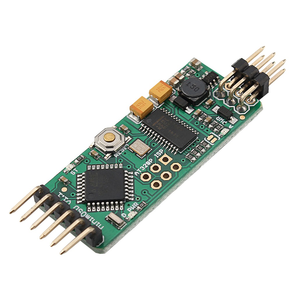
from hk and latest kv osd v2.2 I see text on my goggles but all around text are white patches.Is there any info what should I do to make this patches disappear Thanks. VENDRE Crius MAVLink-OSD V2.1 On-Screen Display MinimOSD. What could be wrong with my minim osd v1.1. Solder jumpers for combining the power sections CRIUS MAVLINK-OSD V2.1 On-Screen Display MinimOSD pour APM Pixhawk MWC Telemetry - EUR 16,70.I didnt have any precision resistors (1), but 5 seems to work fine. Two independent power sections with an LED indicator on each I soldered a voltage divider into the current sensor package R1 - 10k & R2 - 2.2k.It features two independent power and ground sections to isolate the OSD's analog stage: a +5V section for the ATmega and the OSD's digital stage, powered through the FTDI cable or other +5V source and a regulated +5V section for the OSD's analog stage, powered through the video in/out header and capable of handling up to +12V input. Programming is done through an FTDI-compatible 6-pin cable. It's main components are an ATmega328P 8 bit microcontroller with an Arduino bootloader, and a MAX7456 monochrome on-screen display. It's tailored for use with ArduPilot Mega and the MAVlink protocol, and designed to be as small as possible. Its tailored for use with ArduPilot Mega and the MAVlink protocol, and designed to be as small as. Its tailored for use with ArduPilot Mega and the MAVlink protocol, and designed to be as small. This is a mini Arduino based on-screen display board. This is a mini Arduino based on-screen display board. This is a mini Arduino based on-screen display board.


 0 kommentar(er)
